Biotensegrity
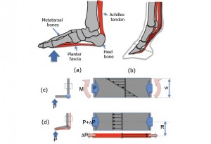
Leg’s musculoskeletal system with an adaptive neuromuscular control employs a synergistic arrangement of bones, muscles, tendons and ligaments to withstand the high ground reaction forces in a relatively light structure. For example consider the anatomical arrangement of the human leg. (See Fig.1) When there is a large load at the metatarso-phalangeal joints\footnote (ball of the foot) during running, the ankle (if foot is considered as rigid body as shown in Fig.1c ) would experience a high moment (roughly 309 N.m for a 70 kg human. Assuming the length between the ball of the foot and ankle is around 0.15m and the maximum ground reaction force is three times of weight. However, the ground reaction force is distributed through the bones, tendons and muscles. As a results plantar fascia, the Achilles tendon and the gastrocnemius muscle carry tension and the bones including Metatarsus bones and tibia are loaded mainly in compression. As the bones have better strength at compression than tension and tendons and muscles have high strength in tension this distribution of the loads provide a design which is strong and light. The tendon also plays an important role in providing necessary compliance and energy storage. The same principle seen in humans (plantigrades) can be seen in unglulates (Nail runners as horse, Fig1.b and digitigrades (e.g. cats and dogs).
Figure.1 A synergetic arrangement of bones and tendons ligaments shown in human (a), and horse foot(b). (c), (d) compare the stress distribution between a conventional robotic leg structure and a tendon reinforced leg structure.
In high speed legged robots, while the legs need to withstand ground reaction forces substantially higher than the robot’s weight, minimizing the leg inertia is highly desirable for high speed locomotion. To achieve high speeds, it is essential to obtain high stride frequencies. High stride frequencies require a very short leg protraction time while in the flight phase. In legged robots, high stride frequency can be made possible in two ways, 1) increasing the actuator capacity, and 2) decreasing the leg inertia. The current state of the art in actuator technology precludes increase in actuator capacity without considerably increasing the overall weight. Hence, decreasing the total inertia of the leg structure is more desirable.
Reducing the mass of the legs is the key technique to reduce the leg inertia. However while decreasing the mass, the structural integrity should be maintained, as the legs must withstand high ground impact forces. Therefore designing a high speed legged robot imposes a serious tradeoff between agility (which requires low inertia) and strength of the leg design (which requires bulky structures). This trade off becomes even more critical in distal part of the leg since it contains more complex articulated features. These features are necessary for providing more functions including smooth collision to the ground, elastic energy storage, and added control.
Most current mechanical designs for legged robots deal with this trade-off by using strong and bulky legs made of high strength to weight ratio materials such as Titanium and Aluminum. In addition, it is well known that compliance in leg structures is of high importance in energy efficient running. Using metals lead to very stiff legs making it necessary to introduce other strategies to introduce leg compliance. An alternative way can be adopting the biomimetic solutions found in nature and using available engineering knowledge to provide a feasible engineered solution.
Some of the characteristics of biological systems such as distributing the load, energy storage, using tensile forces having high strength while being light remind us of some pin-jointed structures such as trusses, Tensegrities and cable structures well known in Engineering. Extraction of such design principles and taking advantage of a synergistic arrangement of bones and tendons has several potential benefits: 1) It allows the legged robot designers to use cheaper materials for the leg structures which are also easier and faster to fabricate (e.g. molding plastics), 2) it decreases the weight of the leg structure and thereby reduces the total inertia which has serious implications in energy efficient running, and 3) It contains the elements that can be used as series elastic to provide compliance and energy storage.
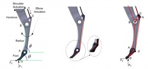
The complexity of the foot structure with its neuromuscular control, however, cannot be resembled easily by available engineering material and knowledge. In order to have a feasible passive leg design some of the concepts noticed in the biomechanics of the leg are adopted and a simplified but feasible design based on the available techniques in Engineering is proposed (Fig.2 and Fig.3). Specifically, two methods for decreasing the weight and inertia of the mobile robot’s legs are tried. First, a bio-inspired leg with tendon is devised (See Fig.2). Second, a new bio-inspired foam-core prototyping method for quick and light fabrication of the leg was implemented to make a lighter leg (See Fig.3).
Figure.2 a. A potential design of the front leg with torsional stiffness at the foot ankle (Point A) b. A bio-inspired leg design c. The approximate schematic of the equivalent pin-jointed structure of the bio-inspired leg.
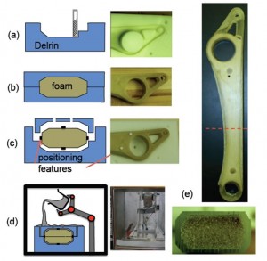 -Figure 3: Fabrication steps for foam-core composite robot structures. (a) mold made by CNC milling, (b) foam-core casted by RTM, (c) positioning disks made of shell material attached to foam part, (d) wireless pouring device inside of the vacuum chamber transfers the resin to the shell mold, (e) complete radius linkage and the cross section
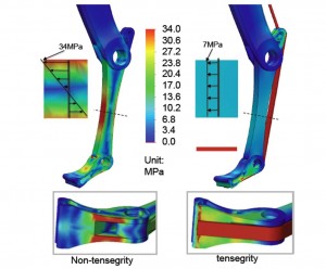
To evaluate the potential performance of the new leg design, static finite element analysis for a specific loading configuration was performed. The results of the finite element analysis for the two design concepts (without and with tendon) are shown in Figure 4. In the tendon- design, the stresses in the radius are much lower and in pure compression at the same location due to the tendon receiving tension force compensating the bending.
Figure 4: FEA analysis of the without tendon-design and with tendon design
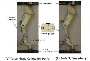
The experimental results of stresses for the same loading configuration on the actual leg were also measured and confirmed the FEM results. (Fig. 5)
Figure 5: Experimental setup for measuring stresses on the Radius for the two design concepts

